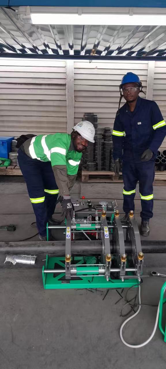
You face severe technical challenges when joining heavy-wall PE100 SDR7.4 pipes. A 355mm outer diameter pipe features a thick wall of 47.97mm. Standard butt fusion machines designed primarily for conventional SDR11 or SDR17 applications may not always provide sufficient available thrust for certain SDR7.4 projects. Machine suitability must be verified through fusion-force calculations and actual equipment specifications.
MM-Tech engineered the High Pressure Thermofusion Welding Machine specifically for these demanding field conditions. This heavy-duty system easily overcomes massive ground drag resistance and eliminates Hi-Lo pipe misalignment. It maintains continuous, stable force during extended pressure-holding cycles. This complete technical guide examines key structural mechanics, essential equipment requirements, step-by-step fusion protocols, and field acceptance standards for high-pressure fluid networks.
Key Takeaways
Heavy-wall SDR7.4 pipes need high hydraulic force to form strong plastic welds.
Ground friction absorbs machine power, so operators must measure drag pressure before welding.
Continuous hydraulic cooling pressure prevents dangerous internal voids inside thick pipe walls.
Rigid machine frames eliminate pipe misalignment and keep pipe ends perfectly aligned.
Smart data loggers record key welding steps to meet strict ISO quality standards.
Engineering Challenges of PN25 SDR7.4 Pipe Welding
Wall Thickness and Cross-Sectional Dynamics
You encounter severe physical challenges when you weld high-pressure polyolefin pipelines. A 355mm SDR7.4 pipe features an ultra-thick wall of approximately 47.97mm. This massive structural dimension expands the annular cross-sectional area far beyond standard SDR11 or SDR17 pipes. You cannot apply standard welding parameters to these extreme profiles.
You must calculate fusion forces based on the actual cross-sectional contact area rather than simple pipe diameter. Pipeline nominal pressure (PN) ratings do not equal hydraulic gauge settings. You need to calculate exact machine cylinder area, maximum hydraulic system limits, and real interface pressure requirements. Without these precise calculations, your equipment will fail to deliver the proper force.
Heavy Pipe Drag Force and Misalignment Risks
Heavy pipe segments generate extreme friction against the ground. Drag resistance continuously opposes hydraulic movement during the alignment and joining phases. Heavy wall thickness increases pipe weight and exacerbates Hi-Lo misalignment across the joint.
Drag Resistance Level / Scenario | Hydraulic Pressure Impact | Operational & Structural Consequence |
|---|---|---|
High Ground/Roller Friction | Absorbs a substantial portion of total gauge pressure | Requires additional hydraulic force solely to initiate and maintain pipe movement |
Severe Drag Loss (e.g., 50% Drag) | Halves the effective fusion pressure applied to the pipe end | Results in pressure starvation, leading to weak cold joints |
Excessive Mechanical Load | Forces the hydraulic system beyond standard operational design | Causes severe strain on motors, seals, and components, increasing wear |
Jerking/Stuttering Movement | Causes unstable pressure delivery during joining | Generates visually uneven beads, structural defects, and weak weld joints |
You must overcome these drag forces using robust hydraulic output and heavy-duty frame clamping. Strong hydraulic systems prevent frame flexing and eliminate pipe slippage under extreme load.
Deep Shrinkage Voids During Extended Cooling
Thick-wall HDPE pipes absorb massive amounts of heat during the heating phase. The outer pipe surfaces cool and solidify faster than the internal core. This thermal dissipation imbalance creates intense volumetric contraction within the molten center.
Uncontrolled core contraction pulls the internal material outward, creating deep structural voids inside the finished joint.
You must maintain stable, uninterrupted hydraulic pressure throughout the extended cooling cycle. Continuous pressure forces molten polymer into the cooling joint core. This action prevents internal void formation and secures total structural integrity.
Architecture of the High Pressure Thermofusion Welding Machine
Heavy-Duty Frame and Clamp Rigidity
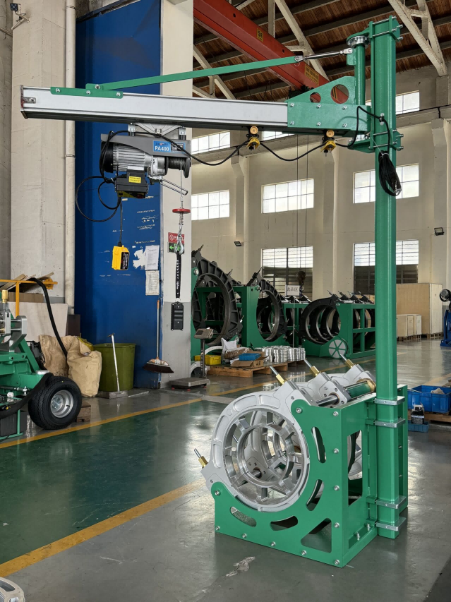
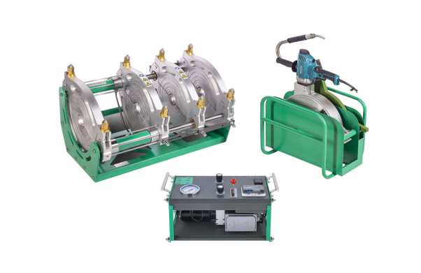
You need exceptional mechanical rigidity to handle heavy 355mm SDR7.4 pipes with thick 47.97mm walls. The MM-Tech 90-355mm heavy-duty four-clamp chassis provides extreme structural stiffness during demanding field operations. Conventional chassis designs flex under extreme hydraulic forces, but this reinforced frame maintains absolute parallel alignment. Heavy-duty clamps and dedicated reduction inserts lock long pipe sections firmly into position. The rigid construction prevents chassis deflection under load and completely eliminates Hi-Lo pipe misalignment across the joint interface. You maintain perfect concentric alignment even when heavy ground drag pulls hard against the machine frame during the fusion process. In addition, quick-locking mechanical latches secure the reduction inserts in place without shifting under stress. Furthermore, the sturdy clamp geometry distributes high clamping forces evenly around the outer pipe circumference. This action prevents localized pipe ovality and ensures clean, square face contact before facing tool engagement.
Upgraded High-Thrust Hydraulic Power Unit
Thick-wall polyolefin pipe joints demand continuous, high hydraulic force during the joining and extended cooling phases. The High Pressure Thermofusion Welding Machine incorporates an upgraded hydraulic power unit equipped with enlarged hydraulic cylinders and high-output pumps. This high-thrust system supplies massive drive force to overcome intense ground friction and move heavy pipe segments smoothly. High-capacity hydraulic reservoirs prevent oil overheating during continuous operation in hot desert climates. The hydraulic circuit maintains steady operating pressure without pressure drops throughout long cooling cycles.
A precision heating plate works directly alongside the hydraulic system to ensure deep, uniform thermal penetration.
A durable triple-layer PTFE coating prevents molten plastic material from sticking to the plate face during plate removal.
Optimized heating elements maintain consistent plate surface temperatures within a strict ±5 °C threshold across all heating zones.
Advanced electronic controllers prevent surface temperature variation from exceeding a maximum allowable ±5 °C limit, avoiding uneven melt depths.
This uniform heat distribution creates a consistent molten polymer layer across the entire cross-sectional area. You prevent weak cold spots and achieve structurally flawless welds in thick-wall pipes.
Smart Data Logging and ISO 12176 Traceability
Critical high-pressure fluid networks require comprehensive quality documentation for third-party auditing agencies. You can integrate an optional smart Data Logger into the High Pressure Thermofusion Welding Machine to automate essential field data collection. The data logger records critical welding variables in real time and generates detailed PDF or CSV quality reports for engineering review.
To satisfy ISO 12176 traceability requirements for external quality audits, the system logs mandatory data points:
Material and Component Traceability: Scanned barcode data capturing resin batch numbers, pipe manufacturer details, and exact production dates.
Operator Credentials: Welder identification badge data connecting each completed joint directly to a certified technician.
Geographic Data: Precise GPS location coordinates recording the exact geographic site location for every weld joint.
Process and Execution Parameters: Dynamic operational metrics including heating plate temperature, measured drag pressure, target fusion pressure, heat soak duration, and cooling cycle timing.
These detailed digital records deliver total process transparency for site inspectors. You verify strict engineering compliance and prove joint integrity across every section of your piping network.
Primary Applications for SDR7.4 Heavy-Wall Piping
Desalination and High-Lift Water Transfer
You install SDR7.4 heavy-wall PE100 pipelines in coastal desalination projects and high-lift water networks. High-pressure membrane feed systems and long-distance product water transmission lines demand high pressure ratings like PN25. These thick-wall pipes easily withstand severe internal hydrostatic pressures across long elevation changes.
Desert environments subject pipelines to harsh solar radiation and intense 45 °C ambient heat. PE100 materials resist salt-spray exposure and electrochemical corrosion far better than metallic pipes. You maintain smooth fluid delivery over long operational lifespans without structural rust degradation.
Mining Tailings and Slurry Transportation
Mining operations transport high-density slurries over long distances across steep elevations. You face continuous water hammer impacts and internal surface wear from abrasive solid particles. Thick SDR7.4 walls provide exceptional structural safety under these harsh dynamic loads.
High-density polyethylene piping can outperform traditional steel by up to 20 times in abrasive slurry environments. This material absorbs particle impacts and completely eliminates bottom-invert erosion issues that compromise steel and concrete-lined pipes.
Performance Metric | HDPE / PE100 Pipe | Unlined / Carbon Steel Pipe |
|---|---|---|
Abrasion Resistance & Lifespan | 3–7x longer service life in high-silica slurries; absorbs particle energy without surface degradation | Poor to moderate; experiences rapid surface wear and invert erosion |
Impact Behavior | High toughness absorbs kinetic energy and resists crack propagation | Hard and brittle under continuous particle impact |
Failure Mode | Gradual, predictable wear | Catastrophic failure if internal protective linings crack |
The material demonstrates a superior 4:1 sliding-bed wear ratio over standard commercial steel pipes in controlled slurry flow conditions. High-density polyethylene absorbs sliding-bed media impacts and prevents crack propagation. You lower pipe replacement frequency and reduce operational downtime significantly.
Industrial Chemical and High-Pressure Process Lines
Industrial plants specify SDR7.4 pipelines for chemical process networks, cooling water systems, and industrial wastewater treatment lines. The thick wall profile handles high operational pressures and surge transients safely.
You must confirm chemical compatibility, medium concentration, and operating temperature with the pipe manufacturer before installation. Robust fusion joints protect your facilities against hazardous fluid leaks.
Step-by-Step Fusion Protocol with High Pressure Thermofusion Welding Machine
Facing, Alignment, and Drag Calculation
You must execute a precise fusion procedure when joining heavy 355mm SDR7.4 pipes with an ultra-thick 47.97mm wall profile. You clamp the heavy pipe segments securely into the rigid four-clamp frame. Next, you insert the electric facer tool to shave both pipe ends until you achieve clean, continuous plastic shavings. You verify parallel face contact and inspect axial alignment to eliminate Hi-Lo mismatches across the joint.
Drag pressure represents the exact gauge reading necessary to overcome system resistance and move the carriage holding the pipe. Severe ground friction absorbs significant hydraulic energy on site. You must measure this drag pressure value dynamically before initiating every thermal heating phase.
Position the faced pipe ends about 50 mm (2 inches) apart by moving the machine carriage.
Set the carriage control valve to neutral, engage heating mode, and dial the middle pressure-reducing valve counterclockwise to its minimum level.
Shift the carriage control handle to the left.
Rotate the heating valve clockwise to raise the pressure incrementally.
Observe when the carriage starts to displace.
Immediately adjust the heating pressure valve counterclockwise until the carriage moves at a minimal, continuous rate.
Document this value as the verified drag pressure.
Calculate the total required fusion pressure by combining the theoretical fusion pressure with the newly recorded drag pressure.
You calculate the correct total setpoint prior to heating using the standardized engineering formula: Total Gauge Pressure = [(Interfacial Pressure × Pipe Surface Area) ÷ Hydraulic Piston Area] + Measured Drag Pressure.
Thermal Penetration and Heat Soak Timing
You insert the PTFE-coated heating plate once you establish your exact hydraulic pressure settings. The High Pressure Thermofusion Welding Machine delivers controlled, uniform heat across the entire cross-sectional contact area. You bring the pipe ends into firm contact with the heating plate to build an initial melt bead around the full circumference.
You reduce hydraulic pressure to near zero after forming the required initial bead height. This adjustment initiates the heat soak phase. Heat must soak deeply into the 48mm wall thickness without pushing molten polymer out of the joint interface. You maintain heating plate surface temperatures within a strict ±5 °C threshold across all heating zones. You must ensure total surface temperature variation never exceeds the allowable ±10 °C maximum limit. Deep thermal penetration creates a consistent plasticized core across the heavy wall.
Rapid Changeover and High-Pressure Cooling
You retract the heating plate quickly after completing the heat soak timer. Rapid changeover prevents the molten polyolefin surfaces from cooling prematurely in open air. You immediately drive the molten pipe ends together using your High Pressure Thermofusion Welding Machine. You ramp up hydraulic output smoothly to reach your target total fusion pressure.
You must maintain sustained, uninterrupted pressure throughout the extended cooling cycle. Thick-wall pipes cool slowly from the outer surface inward toward the center core. Uncontrolled thermal contraction pulls material outward and creates deep structural voids inside thick joints. Continuous hydraulic pressure forces molten material into the solidifying core to counteract volumetric shrinkage. You lock the hydraulic controls and prevent all joint movement until cooling finishes completely. This disciplined execution secures defect-free joints for high-pressure networks.
Middle East Field Proof and Pressure Acceptance
High-Temperature Desert Installation Conditions
You often deploy high-pressure product water transmission lines in harsh Middle East coastal and desert environments. Intense solar radiation drives ambient temperatures up to 45 °C during peak installation hours. These extreme field conditions affect both machine operation and polyolefin material behavior.
High ambient heat accelerates surface oxidation on exposed pipe ends. You must complete the facing process quickly to prevent immediate contamination. The high thermal load also alters hydraulic oil viscosity within the power unit. Modern high-thrust machinery utilizes high-capacity cooling reservoirs to maintain stable hydraulic system pressures despite intense surrounding temperatures.
Hydraulic Alignment and Temperature Compensation
Heavy 355mm SDR7.4 pipes with an ultra-thick 48mm wall profile present severe handling difficulties in extreme heat. Direct sunlight causes uneven thermal expansion along the top surface of long pipe segments. This thermal differential creates subtle pipe bowing, increasing Hi-Lo misalignment risks at the joint.
Heavy-duty reduction inserts lock the thick wall pipe into perfect concentric alignment inside the rigid chassis. You must apply controlled hydraulic thrust to hold the pipe securely against thermal bowing forces. Operators must also calculate daily ambient temperature variations to adjust heat soak durations and heating plate parameters correctly.
Hydrostatic Testing and Acceptance Standards
You cannot evaluate completed PE100 pipelines using standard rigid metal pipe pressure drop criteria. Polyethylene exhibits viscoelastic creep, causing pipe walls to stretch slightly under continuous internal load.
Phase / Mechanism | Material Behavior | Effect on Hydrostatic Pressure Reading |
|---|---|---|
Sustained Pressure Load | PE100 molecular chains stretch and align under stress | Pipe diameter undergoes slight dilation over initial hours |
Volumetric Expansion | Internal volume of the pipe increases while containing a fixed water volume | Gauge pressure naturally decays without any fluid loss |
Testing Interpretation | Misinterpreting normal creep expansion as a system defect | Sound PE lines fail standard rigid-pipe (steel) test criteria |
You evaluate high-pressure network integrity through standardized stabilization protocols rather than simple zero-pressure drop assumptions:
Initial Pressure Stabilization: Maintain the target test pressure for an initial 3-hour period to allow for material stretching.
Pressure Decay Compensation: Periodically add make-up water at hourly intervals to counteract natural creep and bring gauge pressure back to the target level.
MM-Tech delivers zero-defect joints on SDR7.4 ultra-thick-wall pipelines. Our High Pressure Thermofusion Welding Machine combines robust hydraulic thrust with structural chassis rigidity. You achieve precise alignment and eliminate internal cooling voids across high-lift infrastructure networks. Precision digital thermostats maintain stable 220–230°C heating plate temperatures. Robust 0 to 16 MPa hydraulic systems ensure continuous fusion pressure. Smart data logging guarantees ISO 12176-1 and DVS 2207 digital traceability for third-party auditing.
Submit your exact pipe outer diameter, SDR, material grade, and site drag estimates to MM-Tech today. Our technical team calculates custom hydraulic machine sizing and provides competitive project quotes immediately.
FAQ
Why do PN25 SDR7.4 pipes require higher welding force than SDR11 pipes?
A 355mm SDR7.4 pipe features an ultra-thick wall of about 47.97mm. This profile expands the annular cross-sectional contact area significantly compared to SDR11. Under the same interface pressure, the machine must deliver much higher theoretical fusion force to join the pipe ends successfully.
How does the High Pressure Thermofusion Welding Machine prevent internal shrinkage voids?
Thick walls cool slowly from the outside inward. Thermal dissipation imbalances cause internal volumetric contraction. The High Pressure Thermofusion Welding Machine maintains continuous hydraulic force throughout the extended cooling cycle. This action forces molten polymer into the solidifying core and prevents internal void formation.
Why must you calculate site drag pressure before heating?
Ground friction and pipe weight resist hydraulic movement during fusion. Drag force absorbs a large portion of system pressure. You measure actual drag pressure dynamically before heating. Then, you add this drag value to the theoretical fusion pressure to calculate the correct total gauge setting.