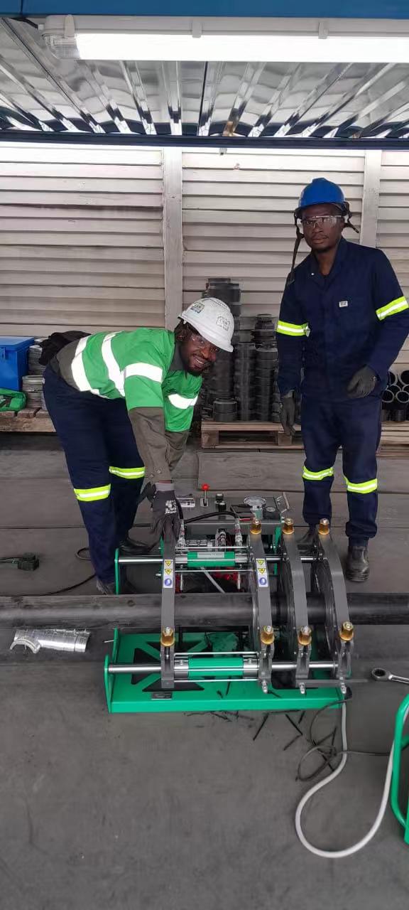
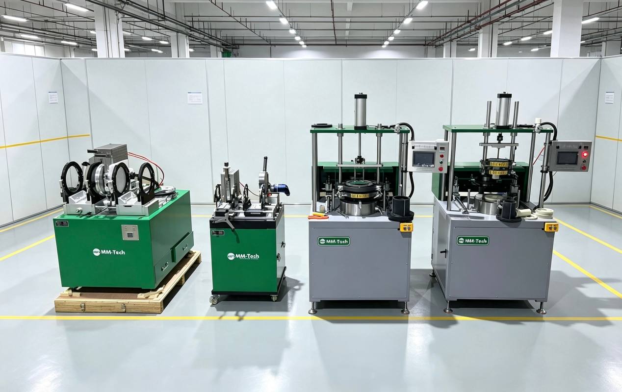
High-purity industrial piping systems require total cleanliness across every plastic pipe network. Traditional hot-plate welding often sticks to melted materials. This direct touching brings unwanted dirt particles into your ultra-clean fluid lines. You solve this major quality problem by switching to a non-contact method.
The MM-Tech IRW-110 infrared welding machine offers an exact solution for joining advanced polymers. This flexible tool safely handles pipe sizes from 20 mm to 110 mm. Radiant heat warms the surface faces evenly without physical touching. You create strong, dependable joints across all production cycles. Follow these simple steps to complete the whole assembly process safely.
Key Takeaways
Position clean plastic pipes inside the machine holders with care before trimming them.
Trim pipe ends evenly to create smooth surfaces for radiant heating.
Use non-contact infrared heat to warm the ends of plastic pipes evenly.
Quickly push the heated pipe ends together using steady pressure, and let them cool down naturally.
MM-Tech IRW-110 Infrared Welding Machine Setup and Clamping
Fixture Adjustment and Diameter Inserts
Start setting up the MM-Tech IRW-110 infrared unit by unboxing it carefully. Place the main frame on a steady, flat work table. Choose the correct clamp inserts for your pipe’s exact outer size. This machine easily handles polymer sizes from 20 mm to 110 mm (1/2″ to 4″ IPS). Swapping inserts for different jobs takes very little time. Using the right insert stops surface scratches while holding the pipe tightly during work.
Put high-purity plastic pipes like PP, PVDF, and PFA into open clamps. Tighten top screws evenly to hold every plastic piece in place. Check clamping tightness so you do not crush thin pipe walls. Equal clamping pressure stops pipes from spinning during fast face milling. Automatic controls help your work by keeping clamping positions identical for every single job.
Pipe Extension and Coaxial Alignment
You must place plastic pipe ends properly inside the open clamp setup. Let the plastic pipe stick out 10–12 mm past the inner clamp edge. Measure this extra length carefully so the facing tool cuts accurately. This gap leaves enough room for the rotary milling blades to turn safely. Good spacing permits clean facing cuts without hitting solid metal clamp edges. Proper preparation protects machine parts and gives you a strong joint.
Next, check that both clamped plastic pipes line up straight before milling starts. Match the centerlines of both pipe ends perfectly along the flat surface. Straight alignment removes crooked angles before heat fuses the parts together. Accurate setup ensures equal radiant heat distribution across the entire pipe face. You get a reliable fusion joint every single time. Good prep work builds a strong joint that keeps pure fluid lines safe. This simple setup helps your infrared welding machine run smoothly for great results.
Precision Pipe Milling and Surface Preparation
Planar Facing for Continuous Shavings
You move the electric milling tool directly into the center space between the clamped plastic ends. Turn on the main motor switch to activate the spinning facing blades. Slide the two fixture clamps inward toward the rotating cutter using steady hand pressure. The sharp blades quickly remove uneven surface layers and prepare clean, flat fusion interfaces without damaging the pipe walls. You easily form smooth, flat surfaces on pure materials like PP, PVDF, and PFA without damaging walls.
Watch the cut material peel away smoothly from the turning cutter while you work. You must continue facing until long, unbroken plastic ribbons come out of both sides. Stop pushing clamps forward when the limit screw touches the left and right clamp bodies. This built-in mechanical stop ensures exact parallel alignment across both pipe end faces. This careful prep step sets up your plastic parts for smooth non-contact heat.
Maintaining Clean Fusion Interfaces
Turn off the electric motor switch and move the cutter tool back into its resting rack. You must check the newly trimmed pipe ends right away under bright light. Make sure there are no gaps, deep lines, or uneven spots across the area. Never touch the trimmed plastic faces with your bare hands or dirty gloves. Body oils, grease, and flying dirt completely ruin ultra-clean fluid piping systems.
Wipe away loose plastic chips using oil-free cleanroom towels or clean nitrogen air. You must stop tiny dirt bits from sticking to the soft melting areas. High-purity chemical lines need totally clean surfaces to form a solid chemical bond. Strong surface prep helps you finish a reliable weld every single time. Regular cleaning habits protect every weld against hidden internal flaws. Careful handling ensures your finished pipe joint meets strict quality rules.
Non-Contact Infrared Heating and Temperature Control
Non-Contact Infrared Radiant Thermal Transfer
You place the special radiant heater directly between the two lined-up pipe ends. The MM-Tech IRW-110 uses modern heating technology to warm plastic faces without touching them. Plastic surfaces never touch the actual heating unit during this entire heat cycle. Old hot plates touch plastic directly and leave burnt material behind. This clean method stops material from sticking at all. Clean work prevents tiny dirt particles inside your super-clean piping network. You protect important liquid pathways from dangerous dirty bits during every build.
You push the clamped pipe ends inward toward the central heat source. You must keep an exact gap between the heating plate and plastic faces. The plastic material absorbs heat energy across the entire end surface. Radiant heat warms the plastic walls in an even manner. Surface material softens uniformly without damaging sensitive plastic structures inside. Heat energy moves smoothly into the inner structure of the pipe wall.
Careful distance control gives you complete melt-loss management every time. Softened material stays stable on the open pipe edge. Heat energy goes deep into the wall structure without causing bad wall collapse. You make a smooth melt area across small and large pipe sizes. Equal heat depth prepares both pipe ends for a strong weld. Steady heat exposure removes cold spots across thick pipe walls.
Temperature Controller Setup and Parameter Setting
You set the heat profile using the digital temperature controller. Press and hold the SET key for over 3 seconds to open setup mode. The digital screen shows the active target numbers right away. You push the ▲ or ▼ keys to raise or lower these numbers. Push the SET key again to save your final choices in system memory. Exact digital setups prevent bad heat processing on expensive pipe materials.
Different super-clean plastic materials need specific heat energy settings:
Polymer Material | Processing Profile Focus | Heat Absorption Characteristics |
|---|---|---|
Polypropylene (PP) | Moderate thermal energy | Uniform surface melting across full wall thickness |
Polyvinylidene Fluoride (PVDF) | High thermal energy | Precise melt-flow control without chemical degradation |
Perfluoroalkoxy (PFA) | Strict thermal control | High-heat absorption requiring steady radiant balance |
You choose the best heat for your target material to get correct melting softness. The machine keeps steady heat output during the whole heating cycle. Modern automated controls handle complex heat times to ensure total operator safety. Consistent power output protects material purity levels for tough factory uses. Steady power control keeps sensitive plastics safe from accidental damage during heating.
The system tracks main heat details during the entire joining process. You watch time counts and heat levels continuously on the screen display. Stable heat transfer creates a perfect melted plastic pool. You make a safe weld joint with dependable overall strength. Proper setting choices stop bad weld defects. Quick visual checks confirm even melting before tool pulling starts. You prepare the soft pipe ends for fast force application. Every finished weld holds up against high inner working pressure. You check the melt pool before the final weld seal sets. You keep total control over the whole infrared welding machine process from start to finish. You follow strict welding rules to protect the joint area. Proper heat control builds strong chemical bonds across the final seam.
Force-Controlled Joining and Shielded Cooling
Rapid Transition and F5 Pressure Application
You complete the non-contact heating phase quickly to start the joining stage. Immediate movement protects softened plastic interfaces from heat loss. You slide machine carriages apart and pull out the radiant heating plate smoothly. You must remove the heater without touching softened pipe surfaces. Right after heater removal, you push the open carriage forward to touch heated pipe ends together. High-purity plastics lose surface heat quickly in room air. You must work fast during this step to stop cold spots across molten faces.
The changeover time—the interval between removing the heater plate and bringing the pipe ends together—is strictly regulated to a maximum of 3–8 seconds, depending on pipe diameter. Exceeding this limit causes the molten surface to cool, forming a ‘skin’ that prevents proper fusion.
You touch plastic ends together using light initial force. Next, you increase the joining force steadily according to the specified welding parameters. You increase force until the pressure gauge reaches your target welding force F5. Advanced welding equipment needs smooth force to prevent sudden material squeeze-out. Pushing too hard squishes warm plastic out of fusion boundaries. Proper pressure control holds soft plastic inside the fusion area. You preserve material alignment while creating a neat internal melt bead profile. Follow standard welding steps to keep steady hand pressure until reaching full force F5. Correct force application builds maximum strength across high-purity piping systems.
Natural Cooling under Controlled Clamping
You lock the pressure handle right after reaching target force F5. The locking system holds steady pressure on molten plastic throughout the cooling cycle. Constant force keeps the softening zone compressed while chemical bonds interlock. You must leave pipe clamps locked tightly in place during this period. Moving the pipe assembly too early ruins structural strength in your plastic line. Stable clamping stops axial movement while the molten weld pool turns solid. Proper physical holding creates a strong, even weld joint.
You must cool the weld naturally without using cooling aids. Operators must never spray water or blow air on warm parts. Cold air and water cause fast heat shock inside the hot plastic core. Heat shock creates tiny cracks along the solid weld seam. You protect the active weld surface from outside weather during every cycle. Use protective shields against heavy wind, rain, and bright sunlight. Cold air drafts cool outer pipe walls unevenly and warp plastic shapes.
You watch the timer until the full cooling time finishes. Safe cooling times give long polymer chains enough time to realign properly. You unlock clamp handles only when the weld area reaches room temperature. Release clamp blocks gently to prevent sudden stress on fresh connections. Finally, you remove the completed pipe run from the machine frame. You inspect the clean plastic line carefully and set up equipment for your next task.
Quality Assurance and Ultra-Pure Applications
Visual Bead Inspection and Parameter Verification
You perform a detailed visual inspection right after the cooling phase finishes. You examine the melted bead under bright light to confirm proper radiant heat distribution. A clean, uniform double bead around the joint indicates a successful weld. You conduct a second visual inspection to check bead width and height carefully. Proper bead symmetry confirms that your force application maintained exact coaxial alignment. This initial inspection forms a critical step in your overall qa/qc workflow.
Next, you verify all operational parameters against your defined specifications. You verify the welding parameters according to the defined welding procedure, including heating temperature, heating time, and joining conditions. This systematic approach helps maintain consistent welding quality within your quality control system. You log the precise heating time, target temperature, and joining force for complete process control. Comparing recorded data against set limits ensures long-term reliability for every joint. Documented parameter verification provides full structural traceability for all welded components across your facility.
Semiconductor UPW and High-Purity Chemical Piping
Semiconductor manufacturing plants require ultra-pure water systems with zero particle contamination. You use non-contact infrared radiant heating to eliminate plastic sticking during the welding cycle. The clean melt profile prevents tiny pockets where dirt or bacteria can hide. Your smooth weld seam protects high-purity fluid lines from dangerous micro-particles. Consistent machine execution elevates total weld quality across your ultra-clean fluid lines. Strict operational control delivers exceptional weld quality for critical chemical applications.
High-purity chemical piping systems also demand strict qa/qc standards during field installation. You rely on accurate parameter tracking to maintain solid weld strength across every single pipe connection. Systematic parameter verification lowers operational risks in aggressive acid transportation lines. Quality technicians complete final qa/qc audits by matching joint numbers with digital records. This structured qa/qc process guarantees total compliance for every new weld in complex industrial piping networks.
The standardized MM-Tech IRW-110 process guarantees repeatable, clean joints for ultra-pure applications. You follow simple phases to protect every weld seam. First, you secure accurate pipe alignment inside mechanical clamps. Next, continuous face milling creates flat, smooth surfaces. The non-contact infrared thermal transfer stage warms polymer faces without physical contact. You then execute fast joining under controlled force application. Finally, natural cooling protects your fusion line against thermal shock.
This precise welding process delivers superior weld quality across critical networks. Adhering to these steps improves long-term joint reliability. You eliminate particle contamination risks by choosing an infrared welding machine for high-purity industrial piping installations. Every completed weld holds strong against demanding operational pressures.
FAQ
What pipe materials and sizes can you join with the IRW-110?
You can weld clean plastic pipes like PP, PVDF, and PFA. The MM-Tech IRW-110 tool safely handles pipe sizes from 20 mm up to 110 mm.
Why does non-contact infrared heating prevent surface contamination?
Radiant heat moves thermal energy without touching the heater tool to plastic ends. Polymer materials never stick to hot metal surfaces. You stop burning and keep dirt out of your pure fluid lines.
How do you program temperature parameters on the machine controller?
Hold the SET button down for over 3 seconds to start setup mode. Next, click the ▲ or ▼ buttons to change target numbers. Tap the SET button again to keep your heat numbers saved.
Can you use cold water or air to speed up joint cooling?
You should never spray cool water or cold air on warm plastic. Fast cooling creates thermal shock and weakens the final bond strength. Natural cooling inside locked clamps protects structural integrity for qa/qc tests.
How do you confirm the quality of a finished pipe joint?
Inspect the pipe carefully under bright lighting once cooling finishes completely. Look for a clean, even double bead across the full connection line. Balanced bead shapes confirm good pipe alignment and steady force application.