Using a specialized cnc router eliminates edge melting, chip packing, and rough finishes. The MM-Tech system provides an industrial-grade solution for accurate cnc plastic machining. It handles diverse industrial plastics from 3 mm to 24 mm thick. Processing these plastics relies on material properties, tooling geometry, speed formulas, workholding systems, and hardware features.
Key Takeaways
Single-flute O-flute bits remove hot chips fast and prevent plastic melting.
Proper speed calculations keep tool friction low and protect sensitive edges.
Vacuum workholding systems clamp plastic sheets tight to stop part vibration.
Thermoplastic Compatibility and Material Selection
Acrylic and Polycarbonate Processing
Acrylic and polycarbonate exhibit different thermal behaviors during cutting. Cast acrylic cuts cleanly under controlled heat among clear plastics. Polycarbonate absorbs energy and demands cautious tool engagement over rigid plastics.
For polycarbonate, start with a polished O-flute upcut bit and use conservative engagement. Both chip control and rigidity are critical to avoid cracking and melting, as polycarbonate can be more gummy or chatter-prone than cast acrylic.
Follow these steps when machining technical plastics:
Select a 1/4-inch solid carbide O-flute bit for cutting acrylic.
Set feed rate between 75 IPM (conservative start) and 300 IPM (after testing).
Adjust spindle speed to approximately 18,000 RPM.
Set cutting depth to half the bit diameter (e.g., 1/8 inch for a 1/4-inch bit).
Use ramping techniques during initial penetration to prevent material distortion and reduce stress.
Implement a cooling system (air or mist) to manage heat buildup and prevent melting.
Use multiple shallow passes instead of a single deep cut to reduce stress and improve edge quality.
Ensure proper chip evacuation (e.g., strong extraction, air blast) to avoid recutting and haze.
Polyethylene ABS and High-Density Polymers
Industrial polymers like PVC, ABS, PP, PE, PPH, and PVDF serve diverse needs. Thin plastics measuring 3 mm react differently than thick plastics up to 24 mm. Thermal heat expands soft plastics quickly. Unchecked expansion alters tolerances during large-scale fabrication.
Machining soft polymers requires aggressive chip removal. High-density materials re-weld easily. Vessel manufacturing, ventilation ductwork, marine boards, commercial signage, and custom component assembly rely on clean cuts across all industrial plastics. Proper feed rates preserve essential quality in these plastics.
Tooling and Parameters for Cutting Plastics
Successful cutting plastics requires proper cutter selection and precise thermal management. Machining soft technical polymers creates heat rapidly due to tool friction. Excessive heat causes material smearing, edge distortion, and tool clogging. Operators must balance cutter geometry with active cooling solutions. Air blast cooling systems direct pressurized cold air directly at the tool tip during operation. Compressed air lowers local tool temperatures effectively. Powerful chip collection systems remove warm debris from the cut path instantly to keep workpieces clean. Effective chip removal stops hot particles from resting on the cut edge. Proper chip collection also protects the operator from inhaling floating micro-dust during production runs on industrial plastics.
Single-Flute Geometry and Bit Selection
Single-flute upcut spiral O-flute end mills work best for industrial thermoplastics. Multi-flute end mills have minimal flute area, which traps hot debris and causes material re-welding. A single-edge tool provides maximum flute space to evacuate chips efficiently. This design lowers heat buildup and preserves clean edge finishes across heat-sensitive plastics. Key geometric features improve cutting behavior during machining:
Large chip creation: Generates bigger chips that carry friction heat away from the cut zone.
Ample flute space: Reduces chip packing, clogging, and localized heat buildup.
Upcut flute geometry: Pulls chips upward and out of the cut path efficiently.
Polished flute surfaces: Prevents molten debris from adhering to tool surfaces.
Sharp cutting edges: Minimizes rubbing and friction against soft plastics.
Optimizing CNC Router Speeds and Feeds
Machinists determine safe operational rates through standard mathematical formulas. Feed rate calculations for plastics rely on cutter speed, edge count, and chip load. The core equation states that Feed Rate (IPM) = Chip Load × Number of Flutes × Spindle RPM. A chip load that is too small causes rubbing, friction heat, melting, and premature bit dulling. Conversely, a chip load that is too large causes chattering, rough cuts, tool deflection, and bit breakage. Operators adjust spindle RPM and feed rates based on target material properties:
Material | Spindle Speed (RPM) | Target Chip Load (Inches) |
|---|---|---|
Acrylic (PMMA) | 14,000–18,000 | 0.006–0.010 |
Polycarbonate | 16,000–20,000 | 0.008–0.012 |
HDPE | 18,000–24,000 | 0.012–0.018 |
Delrin (POM) | 18,000–24,000 | 0.010–0.015 |
Smaller tools require higher rotational speeds to achieve efficient cutting action across clear plastics. Larger end mills demand slower spindle speeds to maintain structural stability and extend tool life. Always use sharp tooling because dull cutters generate excessive heat that melts workpiece plastics. Proper parameters prevent material chatter and maintain consistent edge quality across processed plastics. Proper chip removal preserves edge cleanliness and prevents heat re-welding during high-speed production runs.
Key Features of the MM-Tech Plastic Sheet CNC Router
High-Rigidity Frame and Precision Drive
The MM-Tech plastic sheet cnc router uses an integrated high-rigidity gantry to absorb heavy cutting vibration. Precision-ground racks and high-torque gear reducers connect directly to advanced servo systems. This drive transmission delivers high positioning accuracy during fast production runs. Flexible dual-head machining enables efficient processing for complex multi-tool jobs. An automatic quantitative lubrication system pumps oil to moving mechanical parts at fixed intervals. An oil contamination protection tray catches excess drops underneath. This protective tray keeps technical plastics perfectly clean for subsequent welding procedures.
Sensitive electrical components reside inside a sealed cabinet. This clean dust-protected enclosure blocks ambient shop debris from entering delicate circuit boards. Advanced electromagnetic interference protection shields signal wiring against surrounding electrical noise. Consistent control signals preserve tight machining tolerances when routing rigid plastics.
Integrated Vacuum Zones and Smart Software
Grooved guide rails align stock sheets precisely across diagonal reference lines. The heavy-duty worktable contains a 40-hole vacuum layout. Operators adjust the 3-zone vacuum control system to secure small workpieces or full-sized sheet materials firmly. Powerful suction prevents thin plastics from shifting or lifting during high-speed passes. Firm vacuum hold-down eliminates chatter marks along finished edges across soft plastics.
Modern software features streamline everyday sheet fabrication steps. Built-in xOptimizer algorithms generate high-density material layouts directly from CAD files. Automatic CAD nesting functions minimize scrap waste when processing expensive plastics. Smart Projection systems rely on plane recognition technology to locate workpiece origins rapidly. This reliable industrial cnc router accelerates overall throughput while maintaining consistent component quality across all engineering plastics.
Machine Setup Workholding and Defect Troubleshooting
Vacuum Workholding and Static Control
Vacuum workholding provides consistent downward force across large sheet materials. Operators follow a structured setup procedure to optimize suction and control static build-up on the machine bed:
Select a porous MDF spoilboard to allow smooth airflow across all vacuum zones.
Fly-cut both surfaces of the spoilboard to remove factory sealant and maximize vacuum permeability.
Position stock sheets directly over active table grid areas to focus pulling force.
Activate specific vacuum zone valves underneath target workpieces to stop vacuum loss.
Apply auxiliary double-sided tape along thin outer borders to prevent small parts from shifting.
Position ionizer air bars near the cutter to neutralize static electricity across engineering plastics.
Proper vacuum distribution prevents thin sheet materials from bowing upward during heavy cuts. Static charge management keeps plastic shavings from clinging to machine rails and workpieces. Clean work surfaces maintain stable machining conditions throughout long production runs. This reliable setup improves overall part accuracy across processed plastics.
Troubleshooting Edge Defects and DFM Rules
Machinists must identify edge defects early to preserve part tolerances. Excessive cutting heat distorts heat-sensitive plastics, while workpiece vibration causes edge micro-cracks.
Issue | Root Cause | Corrective Action |
|---|---|---|
Heat build-up from chips not clearing | Increase feed rate, reduce spindle speed, improve air blast evacuation | |
Vibration or tool runout | Reduce engagement, improve workholding support, check collet runout |
Operators resolve static dust attraction by installing ionized air blowers directly on the spindle plate to eliminate static attraction across raw plastics. Part lifting stops when machinists add thin onion-skin tabs around small part contours. Edge burrs vanish when operators switch to sharp O-flute end mills for cutting plastics. Proper parameter tuning guarantees smooth surface finishes during industrial cnc plastic machining.
Engineers follow specific design for manufacturability guidelines to eliminate stress concentrations in technical plastics. Proper wall thickness and radius choices prevent premature failure in finished plastics.
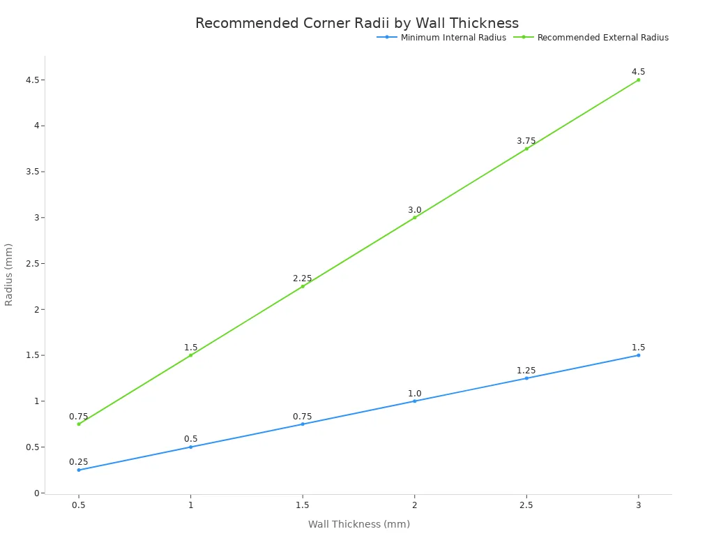
Following standardized geometric rules ensures durable components across structural plastics:
Minimum wall thickness: Maintain a minimum wall thickness of 1.5 mm to prevent wall deflection during machining.
Internal corner radii: Design internal vertical corners with a minimum radius equal to 1 mm or the tool radius to lower stress.
Hole depth ratios: Limit drilled hole depth to 4 times the nominal hole diameter to avoid tool breakage.
Assembly gluing preparation: Lightly sand joint faces prior to adhesive application to create strong chemical bonds across assembled plastics.
Successful plastic fabrication requires single-flute O-flute tooling, high chip loads, clean chip evacuation, and rigid machine structures. The MM-Tech Plastic Sheet CNC Router solves traditional fabrication challenges on engineering plastics through 3-zone vacuum holding, automatic nesting software, and contamination protection. Contact our specialists today to explore optimized cutting systems for your industrial plastics.
FAQ
What sheet thickness can a CNC router process?
The machine cuts thin plastics and thick plastics ranging from 3 mm to 24 mm without thermal distortion.
Which material types work best on this equipment?
Operators process technical plastics including acrylic, polycarbonate, PVC, ABS, PP, PE, PPH, and PVDF for structural components.
Why do single-flute bits benefit heat-sensitive polymers?
Single-flute end mills evacuate warm chips rapidly. Fast chip clearance lowers localized heat when routing high-density plastics during production runs.